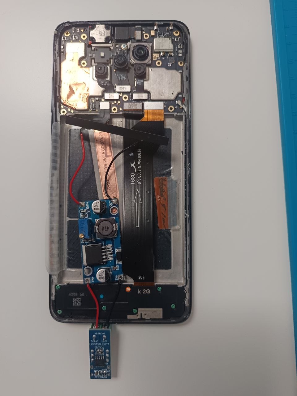
Running the Xiaomi Poco X3 Without a Battery
August 27, 2026
In my previous post, I explained how to install postmarketOS on a Xiaomi Poco X3. While having a Linux-powered mini-PC is great, running it as a 24/7 server presents a challenge: the battery.
Batteries are a point of failure for continuous operation. They can swell over time due to constant heat and charging, or they might fail unexpectedly, causing sudden downtime. For a reliable, “always-on” server, we want to bypass the battery entirely and power the device directly from a stable power source.
Prerequisites
This project requires some basic soldering skills. If you are new to this, I highly recommend watching a beginner’s course like this Soldering Tutorial for Beginners to ensure you don’t damage your hardware.
The Experimentation Process
The idea of “battery-less” mobile devices isn’t entirely new in the enthusiast community. I spent some time researching similar hardware modifications and found interesting implementations of direct power injection on projects like this one. The goal is to mimic the voltage and current characteristics that the Battery Management System (BMS) expects.
Removing the battery and extracting the BMS circuit
To access the internals, you first need to open the back panel. You can do this by carefully using a plastic card (like an old credit card) to pry the edges of the panel away from the frame.
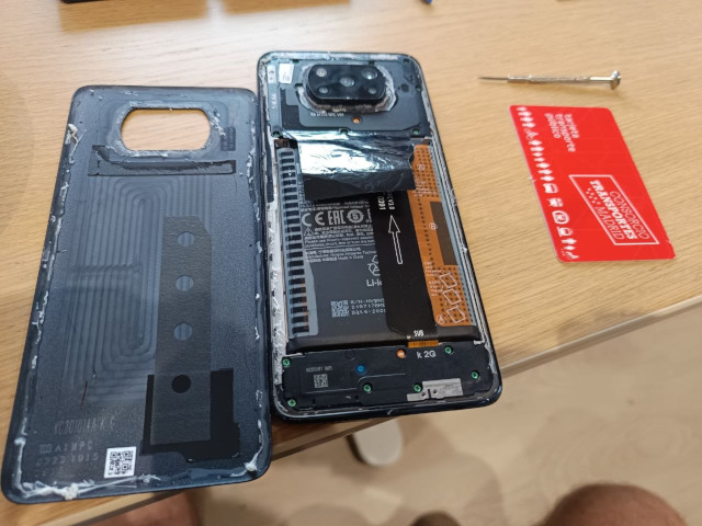
Once the panel is off, remove the screws on the top side to expose the flex connectors. Unplug the flex connectors (e.g. with a small flat precision screwdriver). You can then pull the original battery out (if you need a guide, check out this battery replacement tutorial).
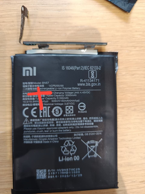
The next step is to extract the Battery Management System (BMS) circuit. This is the small PCB attached to the top of the battery cell. You will need to carefully remove the plastic protection/tape covering it. Once exposed, desolder the old connection or just carefully unsolder by cutting the soldered pads connecting the BMS to the lithium cell using a pair of electrician’s scissors or a similar cutting tool.
Attempt 1: USB-C 5V Input
My first instinct was to simply inject 5V from a standard USB-C charger, step down to 4V using an LM2596 DC-DC Buck Converter, and connect it directly to the BMS pads. However, this failed to boot the device reliably. The phone was stuck in a boot loop; when measuring with a multimeter, I noticed the voltage was unstable, causing the device to reboot constantly. This was likely because the setup could not provide the required current reliably. According to the buck converter’s specifications, a higher input voltage margin (at least 1.5V above the output) is recommended for stability.
Attempt 2: The Working Prototype (USB-C 12V Input)
To achieve a stable boot, I switched to a higher voltage input using a step-down approach.
Components used:
- USB-C PD Trigger Board: A PD/QC decoy board to request 12V from a power delivery source.
- LM2596 DC-DC Buck Converter: Used to step down the voltage to the exact level required by the device.
- BMS Circuit: Instead of using the full battery, I soldered the output of the buck converter directly to the original BMS pads. This allows the BMS to communicate with the motherboard via its original flex connector.
The Setup:
- Configure the PD trigger board to output 12V.
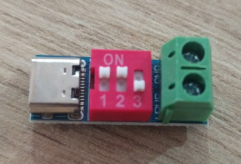
- Feed the 12V input into the LM2596 Buck Converter.
- Connect the output of the buck converter to the battery contact points on the BMS.
- Using a multimeter, adjust the converter to output a stable 4.0V (mimicking a partially charged battery).
- Reconnect the original BMS flex connector to the motherboard.
Final Result
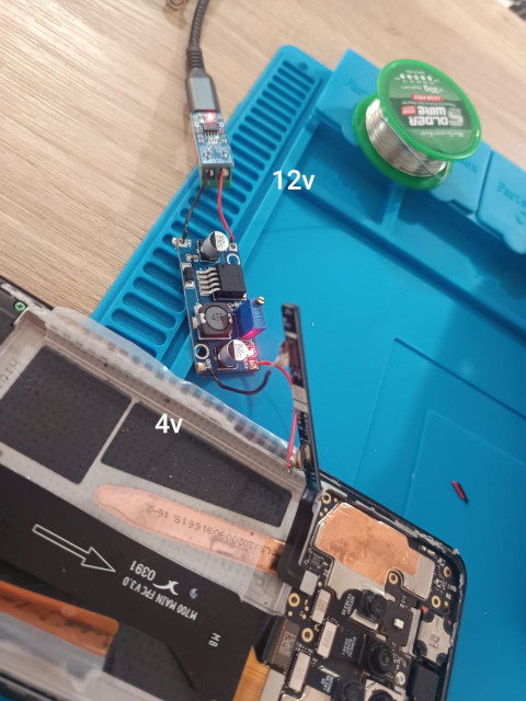
The device now boots from the 12V source and runs perfectly stable without a physical battery attached. This setup is much safer for long-term 24/7 server operations, as it eliminates the risk of battery swelling and provides a consistent power supply.